


Accurately reading construction drawings for takeoffs is a foundational skill every estimator and construction student must master. Drawings are the universal roadmap for a project; they communicate design intent, exact dimensions, materials, safety requirements, and regulatory compliance in a single shared language used by architects, engineers, field teams, and other key stakeholders. But drawings represent intent, not the final built reality—accurate estimating also depends on interpreting them in the context of specifications, RFIs, coordination notes, revisions, and any known information gaps.
Misreading or misinterpreting drawings remains one of the industry’s most expensive and avoidable issues. The Construction Industry Institute found that nearly 30% of project rework comes from incomplete or misunderstood plans, often inflating material estimates by 10–15% long before construction begins. And many of these errors stem not from faulty measurements, but from unresolved scope questions, cross-discipline inconsistencies, or undocumented assumptions that were never clarified.
Strengthening your blueprint-reading and coordination practices is one of the most impactful ways to reduce errors and increase bid confidence. A disciplined estimating process treats assumptions as first-class inputs—confirming revisions, identifying missing information, aligning drawings across trades, raising RFIs early, and clearly documenting inclusions and exclusions. This guide breaks down how to read construction drawings for takeoffs using the correct symbols, sheet types, standards, and workflows so you can extract clean, consistent, and defensible quantities across any trade.
Why reading drawings correctly matters for takeoffs?
Before diving into the technical steps of how to read construction drawings for takeoffs, it helps to understand why this skill sits at the core of accurate estimating.
Every line, symbol, and annotation in a blueprint carries information that guides the entire lifecycle of a project. When estimators understand this information clearly, they can create accurate, competitive estimates that avoid over- or underbidding.
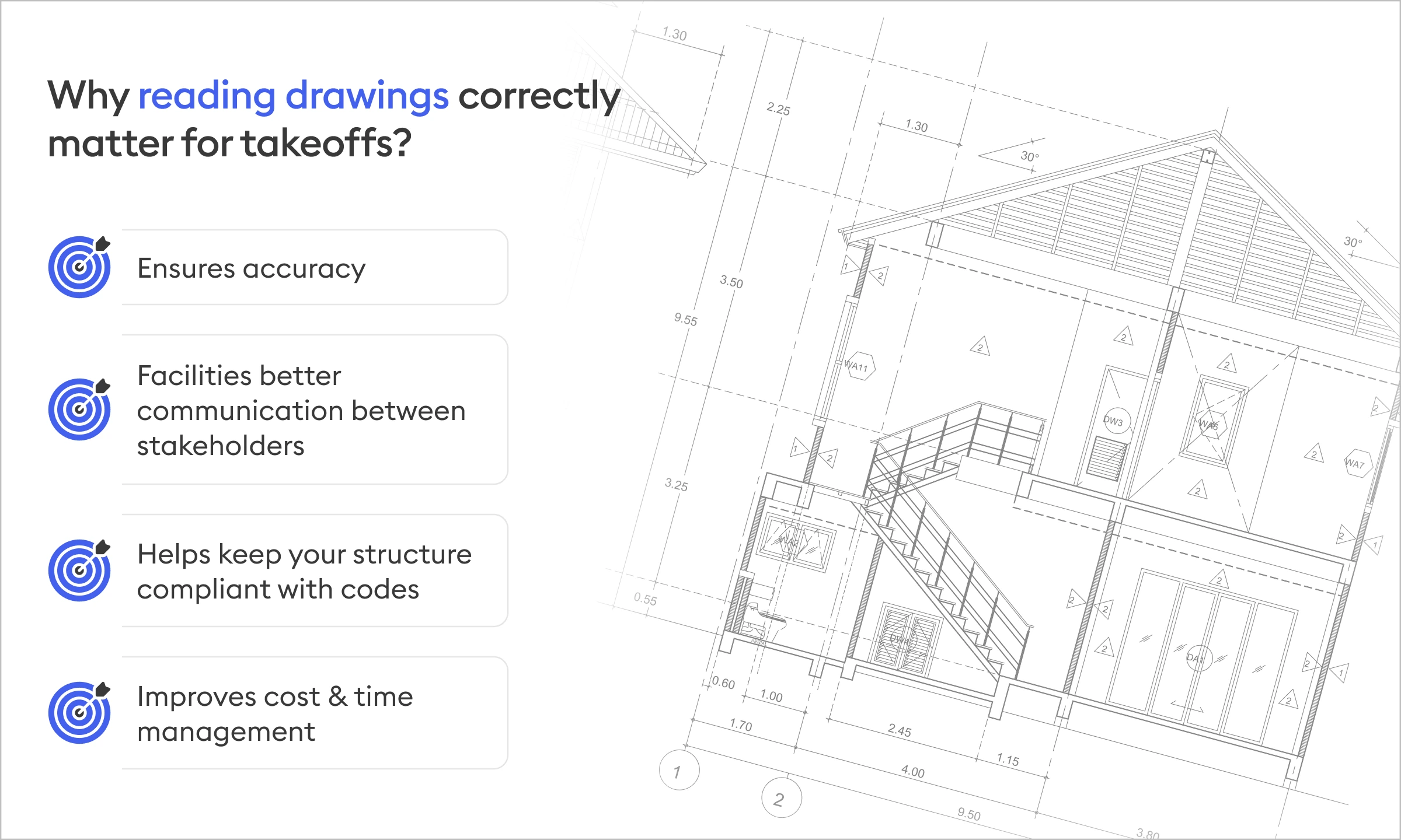
Ensures accuracy
Construction drawings are built around precise dimensions, materials, elevations, and installation requirements. Accurate blueprint reading by estimators ensures you interpret these details exactly as the design team intended. This reduces the risks that stem from assumptions or overlooked notes, allowing every material quantity to be calculated with clarity and consistency.
Facilitates clear communication across stakeholders
Estimators read drawings to define scope and price risk. Project managers read them to plan sequencing. Field crews read them to build. Architects and engineers read them to convey intent. When those interpretations diverge, coordination breaks down fast.
For example, an estimator may assume a wall assembly based on a typical detail, while the field team later discovers a fire-rated variant buried in architectural notes.
Structural connections interpreted one way during takeoff may be clarified differently during shop drawings, triggering RFIs and cost realignment.
MEP clearances misunderstood at bid time often surface during installation, forcing late coordination fixes.
Accurate, consistent reading of drawings creates a shared baseline for conversations, RFIs are raised earlier, assumptions are documented clearly, and decisions are made with fewer downstream surprises.
Ensures compliance with codes and regulations
Accurate interpretation of construction drawings is essential for meeting the regulatory framework every project must operate within. Drawings translate local building codes, zoning requirements, safety standards, and regulatory guidelines. When estimators and project teams understand these drawings correctly, they can identify code-driven design elements, such as fire-rated assemblies, egress paths, accessibility requirements, structural load specifications, and mechanical clearances that directly influence both scope and cost.
When code implications are understood at the estimating stage, teams can price them correctly, clarify intent with designers, and avoid retroactive adjustments that erode trust and margins.
Improve cost and time management
Estimators use drawings to determine what materials are needed, how much labor is required, and, in turn, how long each phase will take. When you understand how to estimate materials from blueprints correctly, your takeoffs, budgets, and schedules become more precise and reliable.
For instance:
Misinterpreting scale or reference details can lead to inflated or understated quantities. Overlooking phasing notes or access constraints can skew labor assumptions. Missing scope coordination between disciplines often results in duplicated or omitted work.
When estimators understand drawings in context, takeoffs become more reliable inputs for both budgeting and scheduling. That reliability reduces rework during revisions, shortens turnaround on addenda, and creates estimates that hold up as projects move from bid to build.
The payoff is predictability, fewer late corrections, tighter control over cost exposure, and schedules that reflect how the project will actually be built.
Understand the basics of construction drawings
Before diving into the different drawing types, you need a strong foundation in the basic components that appear across nearly all plans.
Title blocks: where you get basic interpretation information
The title block appears on every sheet and provides essential information such as:
Core drawing information:
- Title: The name or description of the part or project.
- Drawing number: A unique identifier for the drawing.
- Sheet information: The current sheet number and the total number of sheets in the set (e.g., Sheet 1 of 5).
- Revision information: Details of changes, including the revision symbol, date, and approval for each change.
Project and design details:
- Company/Firm name and logo: Identifies the organization that created the drawing.
- Drafter/Designer name: The name or initials of the person who created the drawing.
- Date: The date the drawing was created or issued.
- Checker/Reviewer name: The name or initials of individuals who reviewed and approved the drawing.
Technical and specification data:
- Scale: The ratio of the drawing's size to the object's real size
- Material: The material from which the part is to be made.
- Finish: Specifications for any required surface finishes.
- Tolerances: General tolerances that apply to dimensions not otherwise specified.
- Weight: The weight of the finished part.
Legends, symbols, and abbreviations
Every drawing set includes symbols that represent materials, fixtures, or assemblies. Understanding architectural drawing symbols meaning is critical because symbols communicate information that may not be written out in text.
Examples include:
- Wall types (e.g., stud walls, CMU walls)
- Door and window tags
- Ceiling symbols
- MEP fixture identifiers
Scales and dimensions
Always verify the scale on each sheet—different drawings within the same set may use different scales. If a drawing is scanned or resized incorrectly, the scale can be distorted; cross-check dimensions against reference measurements or grid lines.
Types of construction drawings and their role in takeoffs

Architectural drawings
Architectural drawings provide the core information required for most material takeoffs. They define the building’s layout, spatial relationships, finishes, and key design elements. Common sheet types include:
- Floor plans – used to calculate flooring areas, wall lengths, and layout-based quantities
- Reflected ceiling plans (RCPs) – essential for ceiling systems, lighting layouts, and HVAC coordination
- Room finish schedules – outline floor, wall, and ceiling materials for each space
- Door and window schedules – specify sizes, types, and quantities for openings
- Interior elevations – clarify finish transitions, wall-mounted elements, and detailed height dimensions
Structural drawings
Structural drawings define the building's load-bearing framework. These sheets translate engineering calculations into buildable elements, showing exactly how the structure must be formed, supported, and reinforced. Key components typically include:
Structural drawings contain the building’s framework. They provide:
- Foundation plans – outlining footings, grade beams, and overall foundation layout
- Slab details and thicknesses – critical for accurate concrete volume calculations
- Beam, column, and connection details – specifying sizes, lengths, and placement
- Rebar schedules and reinforcement diagrams – defining bar sizes, spacing, laps, and quantities
- Structural framing plans – indicating load paths, floor systems, and roof framing requirements
MEP drawings
As buildings become more complex, MEP systems—Mechanical, Electrical, and Plumbing—play an increasingly critical role in both design and estimating. These drawings provide the technical detail needed to quantify equipment, routing, and system infrastructure with precision.
Mechanical drawings show:
- Duct routing – essential for calculating duct lengths, fittings, and insulation
- Equipment locations – such as AHUs, RTUs, and exhaust systems
- Air terminals and diffusers – necessary for supply/return counts and placement
Electrical drawings show:
- Power layouts – showing circuits, receptacles, and equipment feeds
- Lighting fixture plans – used for fixture counts and lighting controls
- Panel schedules and risers – detailing loads, breaker sizes, and distribution paths
Plumbing drawings show:
- Pipe routing – for sizing and quantifying supply, waste, and vent lines
- Sanitary and water systems – showing mains, branches, and connection points
- Fixture diagrams – specifying counts, types, and installation details
Site drawings
Site drawings provide the civil and infrastructure context needed to understand how a building interacts with its surrounding environment. They address everything outside the building footprint and are essential for trades involved in earthwork, utilities, landscaping, and exterior improvements. Key components typically include:
- Grading plans – showing existing and proposed elevations, cut-and-fill requirements, slope adjustments, and drainage patterns
- Utility layouts – detailing underground water, sewer, gas, electrical, and communication lines, along with connection points and depths
- Stormwater management systems – including retention/detention basins, piping, inlets, manholes, and flow directions
- Hardscape and paving plans – outlining sidewalks, curbs, asphalt areas, concrete pads, and accessibility routes
Detail drawings and schedules
Detail drawings supplement the main sheets with additional specificity. They often contain:
- Wall sections – showing stud layout, insulation, sheathing, vapor barriers, cladding systems, and transitions
- Roof assemblies – outlining membrane layers, insulation thicknesses, slope requirements, and parapet details
- Waterproofing and envelope systems – indicating drainage paths, flashing, sealants, and moisture protection layers
- Exterior façade systems – specifying cladding materials, attachment methods, joint treatments, and finish requirements
A step-by-step guide to performing takeoffs from drawings
Now that we have covered the basics of construction drawings, let’s get into the meat. Here’s a beginner-friendly guide to performing takeoffs from drawings in construction.

Review project scope and specifications
Before touching a single sheet, start with project specifications, which are the narrative of a project, describing precise terms, materials, performance requirements, installation methods, and standards that shape every quantity you calculate. They span Divisions 01–33 of the CSI MasterFormat and often include critical clarifications that never appear graphically on drawings.
According to the Construction Specifications Institute, nearly 60% of material-related discrepancies originate from scope misalignment between drawings and specs. This is why experienced estimators always read the specs first: specifications override drawings when conflicts exist, and failing to recognize this can create significant takeoff errors.
Your job at this stage is not measurement, it's comprehension.
Review all drawing sets and revisions
A common mistake among new estimators is reviewing drawings in isolation. Construction is inherently interdisciplinary: architectural drawings define space, structural drawings stabilize it, and MEP drawings enable it to function. Accurate takeoffs require integrating all of these perspectives.
Begin by verifying revisions. Addenda, bulletin updates, or owner-requested changes can significantly affect quantities. According to FMI research, over 35% of rework stems from working off outdated drawings. To prevent this, ensure every sheet you use belongs to the most current drawing set.
Identify key assemblies and components
Estimators don’t measure materials in isolation; they measure assemblies. An assembly is a combination of materials that form a functional system, and takeoffs are most accurate when you identify these early.
For example, a typical partition line on a floor plan may represent:
- Stud framing
- Gypsum board layers
- Acoustic or thermal insulation
- Vapor barriers
- Fire-rated components
- Finishes (paint, texture)
- Fasteners and accessories
Missing even one component of an assembly can skew your quantity and cost estimate. Identifying assemblies upfront helps you structure your takeoff by system, making it easier to maintain consistency and avoid omissions. This is especially important in multi-trade scopes or phased projects where design intent evolves over time.
Measure using the correct scale and methods
With context and assemblies fully understood, you can begin measuring. This is where precision matters most.
Estimators use four primary measurement frameworks:
- Linear takeoffs for walls, conduits, ductwork, piping runs
- Area takeoffs for flooring, roofing, ceilings, landscape zones
- Volume takeoffs for concrete, excavation, backfill, and subgrade prep
- Count takeoffs for fixtures, devices, equipment, diffusers, valves
One of the best habits you can develop is cross-checking unusual or unclear dimensions across multiple sheets. For instance, a structural slab thickness may differ from the architectural reference, or an MEP routing dimension may adjust to avoid a structural beam. These discrepancies have direct implications for quantity and cost, making precise measurement practices essential.
Cross-reference and coordinate information
Construction drawings do not operate independently. Estimators must develop the ability to move fluidly between sheets and disciplines. This coordination step is where strong blueprint reading for estimators truly becomes visible.
Information is distributed across:
- Electrical drawings (fixture locations, circuits)
- Architectural reflected ceiling plans (ceiling heights, materials, obstructions)
- Schedules (fixture types, manufacturer details, finishes)
When estimating lighting, for example, the fixture count, fixture types, ceiling height, and mounting conditions may be found on four different sheets. If any piece is missed or misaligned, the takeoff becomes unreliable.
Document all assumptions and notes
If takeoffs represent “what” you measured, your notes represent “why” and “how.”
Every professional estimator documents:
- Assumptions made during measurement
- Missing or unclear information
- Clarifications needed from designers
- Inclusions and exclusions
- References to specific sheets or details
This documentation becomes essential during internal reviews, subcontractor pricing, and value engineering discussions. It also preserves continuity—if someone else needs to pick up your work, they should be able to understand the logic behind your quantities instantly.
The rise of tech for accurate takeoffs
For years, estimators have relied on manual measurements and traditional tools like Bluebeam to complete their takeoffs. These kinds of outdated software are fully human-driven and require manual input at every stage. As the construction industry advances toward adopting new tech, there are already better alternatives on the market.
AI-based takeoffs are on the rise, helping contractors save time and bid more with the same team. Take Beam AI, for example. This software is a 100% automated, AI-based construction takeoff software that takes away the most tedious and time-consuming part of your estimating process.
Doing takeoffs with Beam AI is easy. All you need to do is upload your plans and specify the project scope, and you’re done. AI handles everything else.
- Beam AI also gives you a structured Excel that plugs into your estimation workflow with ease.
- Automated addenda handling with a Variance Report that tells you exactly what’s changed and where.
- Discrepancies between what you measure and what’s written on the plan are flagged upfront, so you can clarify early and submit accurate bids.
… and much more.
But Beam AI is not just takeoffs. It includes a full-fledged bid tracking system that helps you track every bid, its status, due date, pending addenda, RFIs, and ITBs in a single, organized dashboard. Automated reminders hit your inbox a day before each deadline so that nothing slips through the cracks.
In alignment with the Bid Board, we have launched a one-of-a-kind system called the Bid Sniper. Contractors get ITBs from various sources, and these cluster your inbox, leading to many missed opportunities. Bid Sniper makes this confusing process easy.
- Automatically captures bid emails from your inbox
- Extracts key bid details using AI
- Organizes everything into a real-time dashboard
- Let's you instantly push qualified bids into the Bid Board
Over 1200 businesses across the U.S. and Canada rely on Beam AI. If you’re interested in how the software works, book a demo now!
Before You Go
Accurate takeoffs don’t begin with measuring or counting; they start with understanding. Understanding the project intent. Understanding the relationships between drawings and specifications. Understanding the logic behind assemblies, dimensions, and details. And ultimately, understanding how all of these elements work together to shape the quantities you calculate.
When you know how to navigate title blocks, scales, revisions, symbols, and drawing coordination, you dramatically reduce the risk of errors that often surface too late—during procurement, submittals, or, worse, construction itself. As mentioned previously, industry data continues to show the consequences of poor drawing literacy. Strengthening this foundational skill is one of the few steps you can take today that has a measurable, lasting impact on takeoff accuracy.
And don’t forget, strong blueprint-reading skills don’t just make you faster, they make you more accurate, more confident, and more valuable to your team. As construction becomes increasingly complex, the ability to interpret drawings with clarity and precision will remain one of the most essential competencies in preconstruction.


.jpg)


.webp)

