




What Are Mechanical Drawings?
Mechanical drawings are the technical documents that describe how a building's HVAC systems are designed and installed. They cover ductwork routing, piping, equipment placement, and the controls that tie everything together.
On most commercial projects, mechanical drawings sit alongside architectural, structural, electrical, and plumbing sheets. Together, these make up the full construction document set. The mechanical sheets are usually marked with an "M" prefix, so M-101, M-201, and so on.
A mechanical set typically comes from a mechanical engineer of record. It gets developed alongside the architectural design and refined through several rounds before it reaches bid stage. By the time it lands on an estimator's desk, it should reflect the current, coordinated scope of the project. That is not always the case in practice, which is part of why careful reading matters so much.
Mechanical estimating and HVAC estimating both depend on this document set being read correctly from the start. A missed note on sheet three can quietly throw off pricing on sheet twelve.
What Does an HVAC Drawing Set Include?
A full mechanical set is built from several distinct sheet types, and each one serves a different purpose. Some show layout. Some show equipment data. Others show how components connect vertically through a building.
Knowing what each sheet type is for makes it much easier to find the right information quickly, instead of hunting through the whole set every time a question comes up.
Some sets also include control diagrams and sequence-of-operations sheets. These describe how the system behaves once it is running, and while they are not always takeoff-relevant, they often explain why certain equipment or dampers appear on the plans in the first place.
How to Read a Mechanical Sheet Step by Step?
Jumping straight into the floor plan is the most common mistake made when reading mechanical drawings. Skipping the setup sheets means missing context that changes how the rest of the set should be interpreted.
As the same sequence is followed every time, a habit is created that catches more scope, much faster.
Step 1: Start With the Title Block
The title block is at the corner of each sheet and contains the basic identifying information. This includes Project Name, Sheet Number, Scale, Revision Number, and Date.
First things first, check the revision number and date. No matter how carefully everything else was measured, a takeoff built from an outdated sheet is a takeoff built on the wrong scope.
Step 2: Review the Drawing Index
The drawing index, usually on one of the first sheets, lists every sheet in the set. It confirms whether the full set has actually been received and shows how the mechanical sheets are organized.
This step takes two minutes and prevents a scenario where a schedule sheet or a detail page gets missed entirely because it was never noticed in the file list.
Step 3: Study the Legend
The legend defines every symbol and line type used across the set. Symbols are not universal. One firm's supply diffuser symbol might look completely different from another's.
Reading the legend first means every symbol on the plan sheets afterward gets interpreted correctly, rather than assumed based on habit from a previous project. This matters most for air devices, where a supply and return vent can look nearly identical — here's why correctly tagging supply, return, and exhaust air is what keeps those counts accurate.
Step 4: Read the Schedules
The schedules are tables of equipment, diffusers, VAV boxes and other items, with their specifications and quantities. This is often where the real counts reside.
Verify schedule entries with plan symbols. If the plan shows twelve diffusers but the schedule shows ten, that discrepancy must be resolved before we can proceed with pricing.
Step 5: Work Through the Plan Views
With the setup complete, the floor plans become far easier to read. Trace duct runs by size and type, note equipment locations, and mark diffuser and grille positions floor by floor.
Work through the set methodically, floor by floor and system by system. Skipping around increases the chance of double-counting or missing a section entirely.
Step 6: Check Sections and Details
Sections and details show how components actually go together. They include details about duct transitions, equipment mounting, pipe openings, etc. All this can change the quantities needed for fabrication or installation.
A detail sheet can show additional details, like rebar or insulation, that never appear on the plan view itself. A detail sheet can reveal extra material, like reinforcement or insulation, that never shows up on the plan view itself.
Step 7: Read the Specifications
Specifications, often bound separately from the drawings, spell out material requirements, insulation types, and installation standards. These do not always show up visually on the plans but directly affect material and labor pricing.
Skipping the specs is one of the fastest ways to underprice a bid, since requirements like duct sealing class or pipe insulation thickness live here, not on the plan sheet.
Following this sequence lines up closely with the framework laid out in a step-by-step breakdown of accurate HVAC takeoffs, which walks through how each of these reading steps feeds directly into a usable quantity takeoff.
What Are Common HVAC Symbols and Abbreviations?
HVAC drawings rely heavily on symbols and abbreviations to pack a large amount of information into a small space. Misreading even one of these can throw off a duct size, an airflow quantity, or an equipment count.
The table below covers some of the most common ones found across mechanical sets.
This is not an exhaustive list. Every project set includes its own legend, and it should always take priority over general industry conventions. Treat this table as a starting reference, not a replacement for the legend on the sheet in front of you. For the full picture, here's a complete guide to HVAC symbols for duct, dampers, and air distribution.
How Do You Do a Takeoff from Mechanical Drawings?
Reading a sheet correctly is the foundation. Turning that reading into a usable mechanical takeoff is the next step, and it is where drawing literacy actually pays off.
From Reading to Quantifying
Every reading step earlier in this guide maps directly to something counted or measured in a takeoff.
- Ductwork: Linear footage by size and type, pulled from the plan views and cross-checked against riser diagrams for vertical runs.
- Equipment: Counted from the plan symbols, then confirmed against the schedule for model numbers and capacities.
- Fittings: Elbows, transitions, and takeoffs are identified along duct runs, often requiring a close read of the details.
- Diffusers and grilles: Counted by symbol type and cross-referenced with the air device schedule.
- Piping: Measured by size and material, with fittings and valves counted separately from linear footage.
A takeoff built this way stays traceable. Every quantity has a source sheet behind it, which matters when a reviewer or a project manager asks where a number came from. The equipment side has its own detailed workflow — here's how to estimate HVAC equipment from the mechanical schedule, from matching tags to pricing freight, rigging, and startup.
Why This Step Is So Time-Consuming
Manual takeoffs from mechanical drawings are notoriously slow. Estimators manually trace duct runs, count symbols by hand, and check schedules line by line. It can take days on a mid-sized commercial project.
That time pressure is exactly where errors creep in. A rushed pass through a 40-sheet set is far more likely to miss a schedule revision or misread a symbol than a careful, unhurried one.
This is also where the industry's staffing pressure compounds the problem. Skilled trades roles, including HVAC technician positions, are projected to grow well above the national average for all occupations, according to workforce research covered by Fortune. Fewer experienced people are available to train the next generation of estimators on how to read a set properly, which puts even more weight on having a reliable, repeatable process.
Where AI Fits Into This Process
This is the point where AI-based HVAC takeoff software earns its place in the conversation. Instead of replacing the reading process described above, it automates it.
Modern HVAC estimating software, including Beam AI, is built to read the same title blocks, schedules, symbols, and plan views an estimator would review manually. It identifies ductwork by size and type, extracts equipment quantities from schedules, counts diffusers and grilles, and flags fittings along duct runs.
This is also where mechanical takeoff software enters the conversation more broadly, since duct, piping, and equipment quantities all live across the same set of sheets and don't need to be pulled by three separate manual processes.
The output is a structured quantity takeoff, built directly from the drawing set, without the hours spent tracing lines by hand. Beam AI's approach to this is covered in more detail in how Beam AI automates HVAC takeoffs, including how it handles ductwork, piping, fittings, and equipment across a full set.
Whether it gets branded as HVAC estimating software or mechanical estimating software, the underlying task doesn't change: read the sheet correctly, then quantify what's shown, consistently, on every set.
This does not remove the need to understand mechanical drawings. It simply shifts where that understanding gets applied. Instead of spending hours on manual measurement, estimators can undertake a focused review of AI-extracted quantities. Estimators still need to know what a VAV box symbol looks like or what a schedule revision means. They just spend less time hunting for it sheet by sheet.
For teams weighing how AI-based tools fit into a broader estimating workflow, a practical guide to choosing HVAC estimating software covers what to evaluate before committing to a platform.
How Does Mechanical Drawing Complexity Vary by Industry?
Reading skill transfers across project types, but what a set actually demands shifts depending on the building it's for. A few examples make the difference a lot clearer and more concrete.
- Healthcare facilities carry some of the densest mechanical sets in the industry. Isolation rooms, redundant air handling, and strict pressure-relationship requirements mean schedules and specs get read far more literally than on a standard commercial job.
- Data centers revolve around precision cooling. Drawings show CRAC and CRAH units, tight airflow tolerances, and extensive controls documentation, since even small quantity errors affect equipment sized for continuous, high-load operation.
- Multifamily and hospitality projects are repetitive rather than dense. The same fan coil or PTAC unit repeats across dozens of nearly identical layouts, so the reading challenge shifts from complexity to consistency across many similar sheets.
- Industrial and manufacturing facilities often tie ventilation directly to process equipment. Exhaust systems, higher-pressure duct classes, and equipment-specific make-up air requirements mean the mechanical set has to be read alongside process drawings, not in isolation.
- Education projects, especially phased renovations, frequently specify dedicated outdoor air systems driven by indoor air quality requirements. Reading these sets means paying close attention to how new equipment ties into existing systems that stay in service during construction.
The reading sequence stays the same across all five. What changes is which sheets carry the real risk, and that's worth knowing before a takeoff begins.
What Are Common Mistakes When Reading HVAC Drawings?
Even experienced estimators fall into a few recurring traps when working through mechanical drawings. Most of these come down to rushing a step that felt optional but was not.
Missing the Schedules
Plan views do not show quantity and specification data that is provided in schedules. By jumping straight to the floor plan, you are missing the model numbers, capacities, and counts that the schedule was intended to clearly communicate.
Misreading the Scale
Duct and pipe lengths depend entirely on reading the plan at the correct scale. A misread scale bar can throw off every linear measurement pulled from that sheet, sometimes by a significant margin.
Overlooking Revisions and Addenda
Mechanical sets change throughout preconstruction. A takeoff built from an outdated revision reflects a scope that no longer matches what will actually get built.
Always confirm the revision number against the latest addenda or bulletin log before finalizing any quantities.
Assuming Symbols Are Standard
Note that symbol conventions differ from one engineering firm to another. Without checking the current legend, assuming a diffuser symbol from a previous project applies here is one of the fastest ways to miscount air devices.

Skipping the Specifications
Specs often carry requirements that never appear visually on the plan sheet, like duct sealing class or insulation thickness. These directly affect material pricing and are easy to overlook when working from the drawings alone.
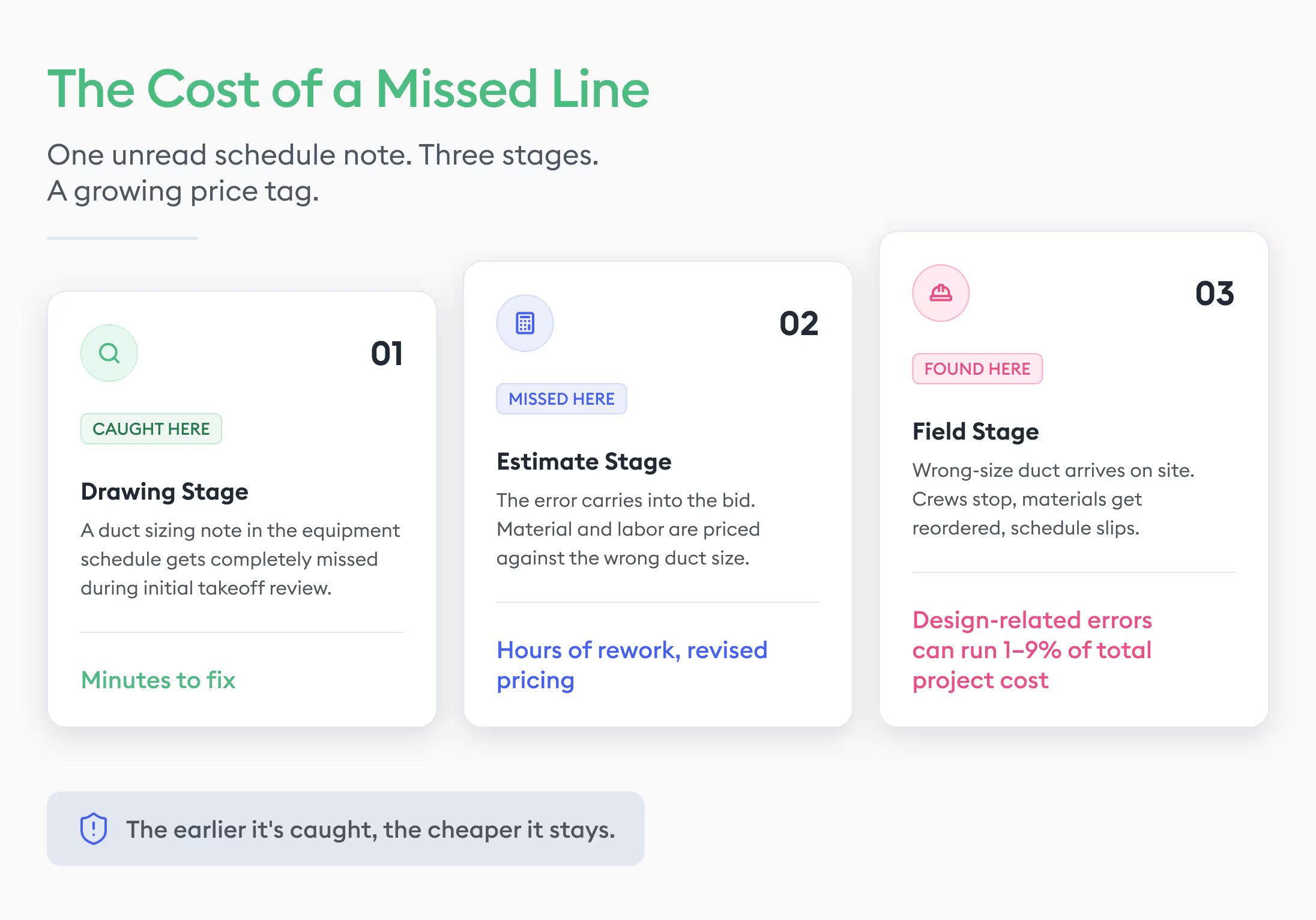
This kind of drawing-stage error is not rare. Design-related issues, including inaccurate drawings and late changes, account for as much as 1 to 9 percent of total project cost, according to industry rework research, a reminder of how much value sits in getting the reading right the first time. Duct construction itself follows its own detailed standards, and SMACNA's recently updated inspection guide for commercial HVAC duct systems is a useful reference for confirming how installed ductwork should match what the drawings specify.
SMACNA has also released updated duct construction standards covering sizing tables and construction options that estimators may see referenced directly in project specifications.
In Closing
Reading mechanical drawings well is a skill that compounds. Every set gets a little faster to work through once the sequence, the symbols, and the common trouble spots become familiar.
That skill is also what makes a mechanical takeoff trustworthy. Quantities pulled from a carefully read set hold up under review, protect margins, and reduce the chance of a costly surprise once the project moves into the field, whether that project is being priced by an HVAC contractor, a mechanical contractor, or an estimating team supporting both.



.jpg)