




How Elevations Help Bring Architectural Designs to Life
When reviewing an architectural drawing set, the floor plan usually gets the most attention. It shows the layout of rooms, walls, doors, and circulation. But there is another drawing that answers a different question: What will the building actually look like from the outside?
That is the job of an elevation.
What Is an Elevation in Architecture?
An elevation in architecture is a two-dimensional, straight-on view of one face of a building. It shows the building’s height, proportions, openings, exterior finishes, roofline, and architectural details without the perspective distortion found in a rendering. Elevations help architects communicate design intent, help contractors understand exterior construction, and give estimators useful information for measuring façade materials.
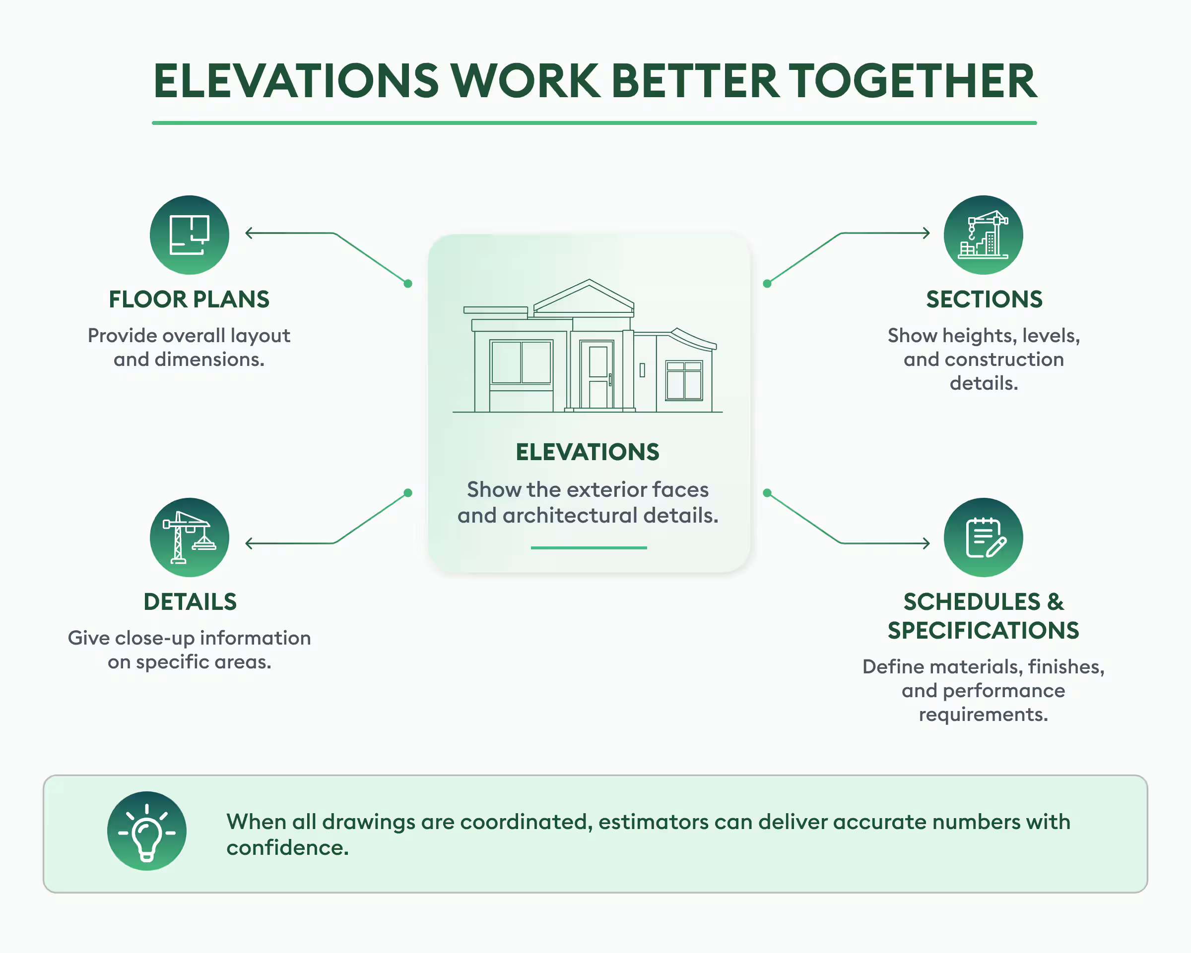
They are also an important part of a coordinated construction drawing set. An elevation rarely tells the whole story by itself, but when read alongside plans, sections, schedules, and specifications, it becomes a valuable source of design and estimating information.
Elevation in architecture is generally created using orthographic projection, which keeps the drawing free from the perspective effects seen in photographs or 3D views.
An elevation drawing can show:
- Exterior walls and finishes
- Windows and doors
- Rooflines and parapets
- Cornices, columns, and balconies
- Dormers and other roof features
- Grade lines
- Vertical dimensions and level markers
- Material changes
- Architectural details and projections
An elevation is not just a picture of how a building will look. It is a working drawing that shows useful details about the exterior, such as dimensions, openings, materials, and other architectural features.
Why Are Elevations Important?
Elevations are useful at several stages of a project. They help teams move from an idea on paper to a building that can actually be priced and constructed.
They make the exterior design easier to understand
A floor plan tells you where a window is located. An elevation shows how that window relates to the rest of the façade.
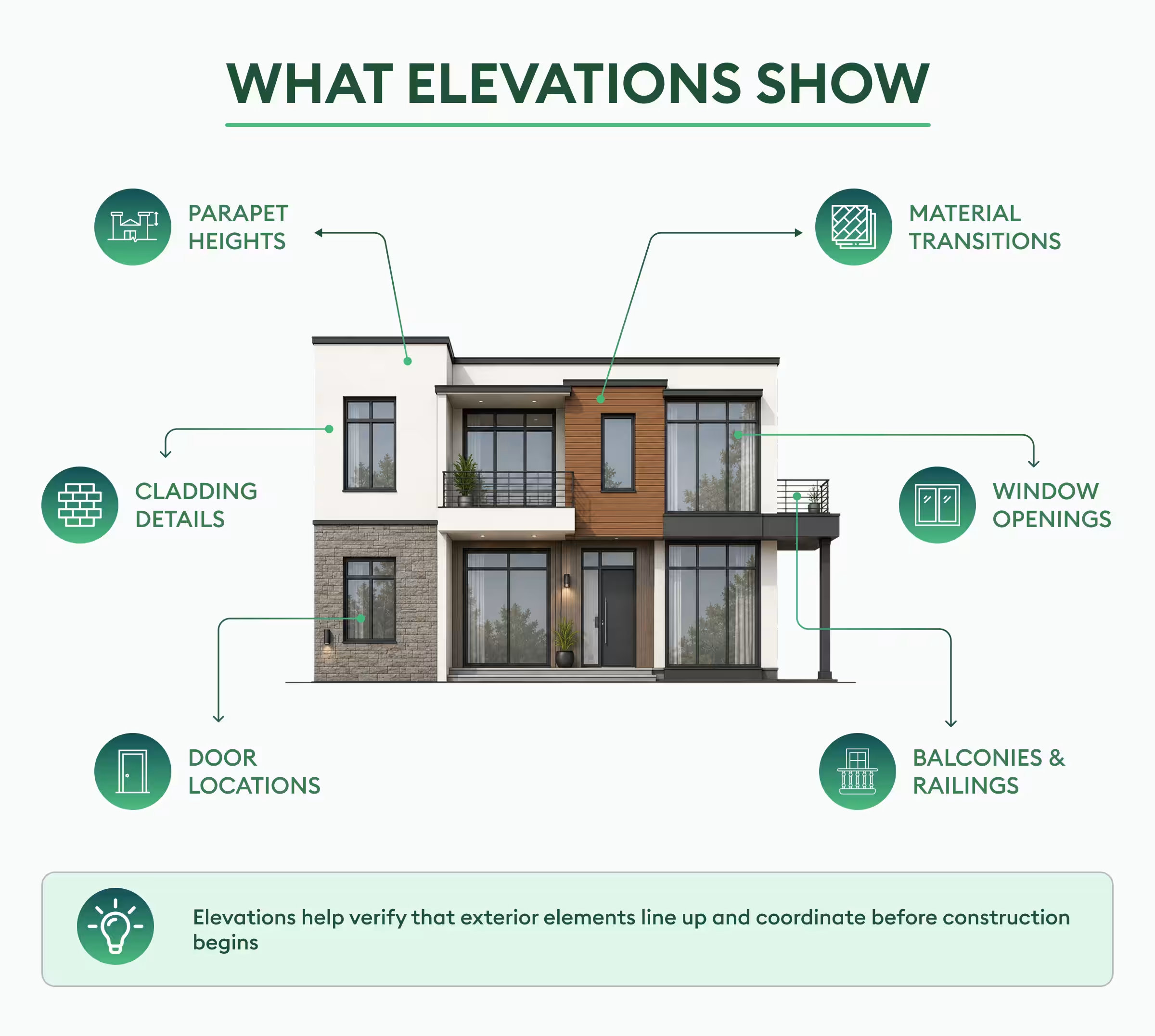
This makes it easier to review proportions, symmetry, window and door placement, roof forms, material transitions, and other visible features.
Clients can also understand the proposed exterior more easily without having to interpret a technical plan.
They help contractors coordinate exterior work
An elevation helps the construction team see where exterior elements should be placed and how they line up with one another.
It can show window and door locations, parapet heights, changes in cladding, cornices, balconies, and other façade details before construction starts.
For construction teams, this information becomes even more useful when it is checked against wall sections and architectural details.
They support approvals and documentation
Elevations give contractors a clear view of the exterior and show how different elements are positioned in relation to each other.
They can be used to check window and door placement, parapets, cladding changes, cornices, balconies, and other façade details before the work begins.
They provide useful estimating information
Elevations can also support quantity takeoffs. An estimator can use them to identify exterior wall areas, façade finishes, windows, doors, cladding, trim, parapets, and other visible components.
However, an elevation should not be used in isolation. Plans, sections, specifications, schedules, and details may contain information needed to confirm the final quantity.
Types of Elevations in Architecture
The types of elevations used on a project depend on the building and the information that needs to be communicated.
Front Elevation
The front elevation shows the principal face of the building, usually the side with the primary entrance or the face most visible from the street.
It often includes the main door, prominent windows, exterior finishes, roofline, balconies, columns, and other features that define the building's appearance.
Rear Elevation
The rear elevation shows the back of the building. It may include secondary entrances, patios, decks, service areas, exterior stairs, windows, and connections to the site.
Although the rear façade may receive less attention from the public, it still needs to be coordinated with the overall design and construction documents.
Side Elevation
A side elevation shows one of the building's lateral faces. Projects may identify these as left and right elevations or use compass directions such as north, south, east, and west.
Side elevations are useful for understanding building depth, window arrangements, roof slopes, wall heights, and changes in exterior materials.
Corner Elevation
A corner elevation shows where two exterior walls meet. It is useful for buildings with features such as wraparound windows, projecting sections, different façade materials, or corner columns.
Since a conventional elevation represents one face, you may need additional views or details to explain complex corner conditions.
Cross-Section Elevation
The term "cross-section elevation" is sometimes used informally, but it is worth making an important distinction.
An elevation shows a vertical face from the outside. A section cuts through the building and exposes what is happening inside.
A section can show floor-to-floor heights, ceiling levels, wall assemblies, structural elements, and other relationships that an exterior elevation cannot fully communicate.
So while both drawings deal with vertical information, an elevation and a section serve different purposes.
What Are the Main Parts of an Elevation Drawing?
The exact elevation drawing components vary from one project to another, but several elements appear regularly.
Walls and Material Hatching
Exterior walls form the main surface of an elevation. Different finishes may be identified through notes, symbols, textures, or wall hatching / material hatching.
Brick, stone, concrete, stucco, siding, and metal panels may each have their own graphic representation. Material callouts are especially important when an estimator needs to separate one façade finish from another.
Fenestration
Fenestration refers to the arrangement of windows and doors within a building façade.
In an elevation, fenestration helps show the size, spacing, alignment, and relative position of openings.
It can also reveal patterns that are difficult to see in a floor plan alone. For estimating purposes, these openings may need to be counted or measured separately depending on the scope.
Rooflines, Parapets, and Dormers
The roof is one of the most visible parts of a building elevation. Drawings may show roof slopes, ridges, eaves, parapets, dormers, chimneys, coping, and other roof-related elements.
These features can affect both the appearance and the construction quantity.
Cornices, Columns, and Architectural Details
An elevation may also include cornices, columns, balconies, brackets, trim, canopies, and other architectural features.
Even relatively small details can affect the estimate if they require additional materials, fabrication, installation, or specialized labor.
Line Weights
Line weights in elevation drawings help distinguish major building elements from smaller or secondary information.
Heavier lines are generally used to emphasize important outlines, while lighter lines can represent secondary details, dimensions, or background information. Consistent line weights make a drawing easier to interpret.
Shading and Shadows
Shading and shadows in elevations can communicate depth and help distinguish recessed or projecting elements. They can also make material changes and façade features easier to understand.
In technical drawings, however, shading should support—not replace—dimensions, notes, symbols, and material specifications.
Elevation in Construction: How Estimators Use It
The role of an elevation in construction extends beyond design communication.
For estimators, elevations can provide useful information for measuring exterior scope.
A façade might contain several different materials, and each area may need to be quantified separately.
Depending on the trade, an estimator may use an elevation to identify:
- Brick and masonry
- Exterior wall finishes
- Metal panels and cladding
- Stucco
- Windows and glazing
- Exterior doors
- Parapets and coping
- Columns
- Exterior trim
- Architectural features
This makes elevations particularly useful when preparing a material takeoff from elevations.
Beam AI's guide to takeoffs & estimating explains how takeoffs turn drawings into measurable quantities that can support budgeting, procurement, and bidding.
How to Calculate Elevation Cost and Quantities
A quantity surveyor or estimator generally begins by identifying the areas and components that need to be measured.
For a simple rectangular wall, the starting calculation might be:
Gross wall area = width × height
If the scope calls for deductions, openings can then be accounted for:
Net wall area = gross wall area − applicable openings
That sounds straightforward, but real façades are rarely simple rectangles.
A building may have different wall heights, stepped sections, projections, recesses, parapets, material transitions, and irregular rooflines. Each condition can change the final quantity.
When calculating elevation cost, combine the measured quantities with applicable material prices, labor, equipment, waste, overhead, and other project-specific costs.
Beam AI's construction estimating guide covers the broader estimating process, including takeoffs, labor and supplier pricing, indirect costs, contingency, and bid review.
How to Calculate Exterior Wall Square Footage From Elevations
When measuring exterior wall area from elevations, first confirm the drawing scale and identify the limits of the area being measured.
From there, an estimator can:
- Identify the wall boundaries.
- Calculate the gross wall area.
- Identify windows, doors, and other openings.
- Deduct openings where required by the scope.
- Separate different materials or finish zones.
- Check the result against plans, sections, and specifications.
This approach is particularly useful for a façade takeoff, where several materials may appear on the same elevation.
For example, a building could have brick on the first floor, metal panels above it, stone around the entrance, and fiber-cement siding at the rear. Treating the entire elevation as one surface would produce an incomplete takeoff.
The elevation helps establish where each material occurs, while other drawings and specifications help confirm how it is constructed.
Elevation vs. Floor Plan vs. Section
These three drawing types answer different questions:
Floor plan: What is the horizontal layout of the building?
Elevation: What does one vertical face of the building look like?
Section: What does the building look like when it is cut vertically?
For example, a window's location can be seen on a floor plan. An elevation makes its appearance and vertical placement clearer.
A section may show its relationship to the wall assembly, floor, ceiling, and structure. Reading these drawings together is important for both construction and estimating.
How to Read an Elevation Drawing
If you are unfamiliar with architectural drawings, you do not need to understand every symbol at once. Start with the information that directly affects the building's exterior.
Check the title and orientation
Determine whether you are looking at the front, rear, side, or another elevation.
Confirm the scale
Always check the stated drawing scale before measuring. Never assume that a printed or on-screen drawing can be measured accurately without verifying its scale.
Find the grade line
The grade line establishes the building's relationship to the ground and provides a useful reference for vertical measurements.
Look for dimensions and levels
Pay attention to floor levels, window heights, roof elevations, parapets, and other vertical dimensions.
Identify openings
Review the location and arrangement of doors and windows. Check schedules when exact sizes or specifications are required.
Identify material changes
Look for hatching, notes, keynotes, and finish callouts that divide the façade into different material zones.
Cross-check other drawings
If something is unclear, check the floor plan, section, detail, schedule, or specification rather than assume.
This last step is especially important for estimating. A drawing may show that a feature exists without providing all the information required to price or quantify it.
Why Elevations Matter When Designs Change
A revised elevation can affect more than the appearance of a building.
Adding a window changes glazing and framing quantities. Increasing wall height adds exterior finish area.
A new parapet can introduce additional wall, coping, flashing, waterproofing, and insulation requirements.
Changing a cladding material can affect both material and installation costs. That is why drawing revisions need to be reviewed as part of the estimating process.
Beam AI's AI and automation guide for construction estimating explains how automated workflows can help teams organize drawings, extract quantities, compare revisions, and keep estimating information aligned with updated project documents.
The objective is not simply to measure faster. It is to make sure the quantities being priced correspond to the latest design.
Final Thoughts
An elevation in architecture is much more than a drawing of a building's exterior. It gives architects, contractors, clients, and estimators a clear vertical view of the building and its façade.
From the front elevation and rear elevation to side and corner views, elevations show how windows, doors, materials, rooflines, parapets, columns, and other features come together.
They are also useful for estimating. When coordinated with plans, sections, schedules, and specifications, elevations can support material takeoff from elevations, façade takeoff, and measuring exterior wall area from elevations.
For estimating teams, the biggest value comes from using elevations as part of the complete drawing set—not treating them as a standalone source of quantities.
That approach gives the estimator a clearer picture of the scope and reduces the chance of pricing something based on incomplete information.
As construction drawing sets become larger and revisions become more frequent, digital takeoff workflows can also reduce the manual work involved in extracting and checking quantities.



.jpg)